


Overview
Accurate combustion analysis is crucial for maintaining heating system efficiency, safety, and performance. Whether commissioning a new boiler, conducting routine servicing, or troubleshooting combustion issues, reliable measurements are essential for effective maintenance.testo 310 (2nd Gen) Printer Kit – Smart Analysis with On-Site Printing
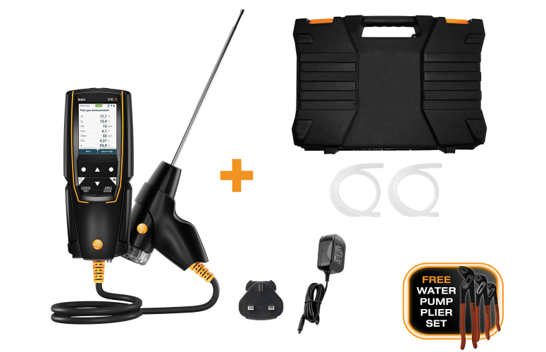
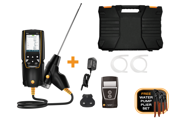
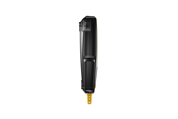
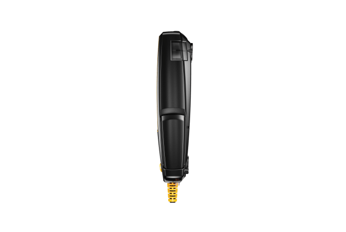
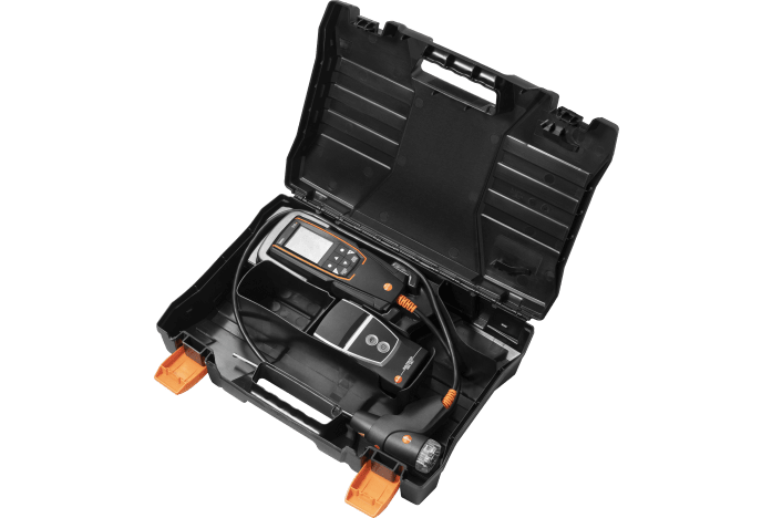
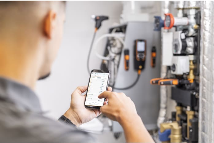
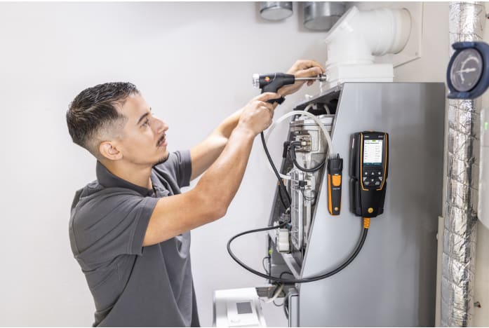
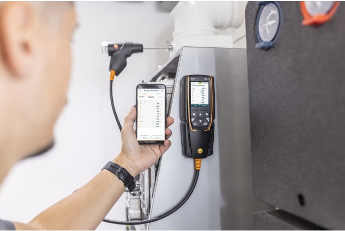
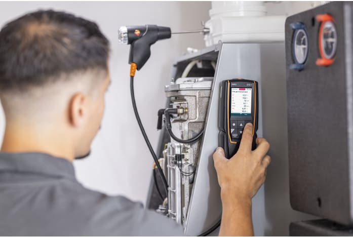
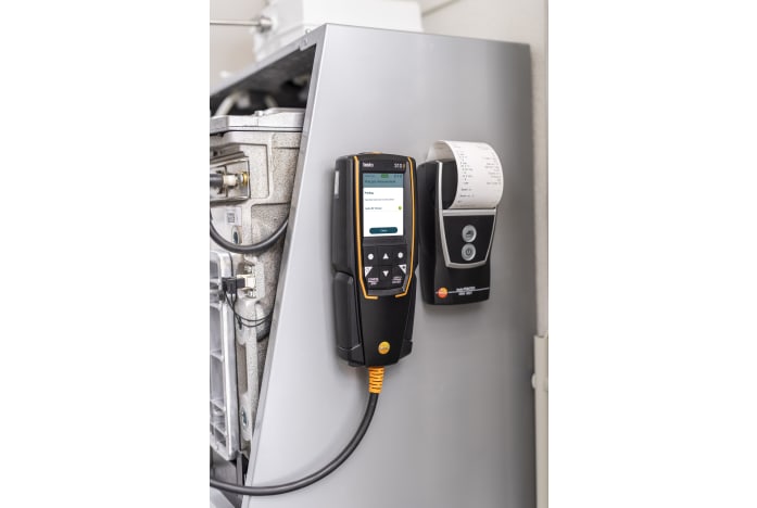
The testo 310 (2nd Gen) Printer Kit combines the trusted performance of the testo 310 (2nd Gen) flue gas analyser with a testo Bluetooth Printer for instant on-site documentation. This complete solution is designed for fast, accurate measurement of combustion values in gas and oil-fired boilers.With four integrated measurement menus — exhaust gas, draft, Ambient CO, and pressure — the testo 310 (2nd Gen) simplifies essential testing tasks. The intuitive colour display ensures clear visibility of all readings, while Bluetooth connectivity allows seamless operation via the testo Smart App. The app enables you to configure the analyser, view real-time results, and generate professional reports directly from your smartphone or tablet.
Instant Results, Instant Documentation
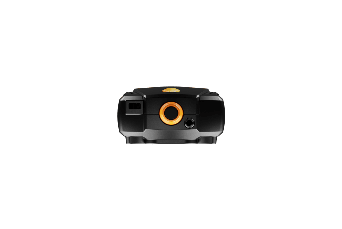
The included testo Bluetooth Printer allows engineers to print results immediately on-site, providing customers with clear, professional documentation in seconds.For added efficiency, the testo 310 (2nd Gen) offers 30-second sensor zeroing, a replaceable probe filter, and a quick-to-empty condensate trap. It can also be paired with testo Smart Probes to measure flow/return temperatures and gas pressure, with results displayed directly in the testo Smart App.
With smart connectivity, fast reporting, and a robust design, the testo 310 (2nd Gen) Printer Kit is the ideal choice for heating engineers looking for an all-in-one solution for flue gas analysis and on-site documentation.