Image
    1. Home
    2. testo 320

    testo 320 - Super efficient flue gas analyzer

    0632 3220
    testo 320
    testo 320
    testo 320 basic
    testo 320 basic
    testo 320 basic
  1. Six applications, one device: flue gas, flue draft, pressure, gas leak detection, CO ambient air and pressure difference measurements
  2. Integrated flue gas sensors with temperature sensor included; ultra-fine pressure sensors and a wide range of other sensors, ports and probes optional
  3. Rugged, high-quality design, high-resolution, multi-color display, self-explanatory menu guide
  4. TÜV-tested according to EN 50379, Parts 1-3 and 1st BImSchV
  5. Temperature measurements at radiators; flue gas parameter and pressure measurements at burners; CO measurements in the ambient air: the testo 320 allows you to carry out all measurements in and around heating systems with only one measuring device.
    The testo 320 flue gas analyzer is a trusty and reliable companion for all those people who specialise in installing, inspecting and servicing heating systems. The high-quality, professional all-rounder is easy to use and allows you to carry out all measurements in and around heating systems with only one device. The testo 320’s special rugged design means that it is excellently equipped to stand up to the rough and tumble of daily use.
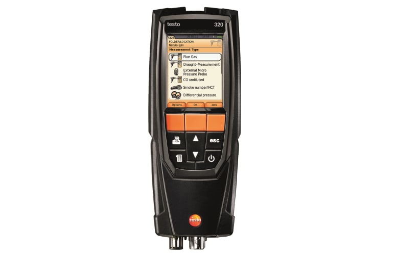
    A set of easy-to-follow, self-explanatory, country-specific menus guide you safely through all the measurements. The readings are all presented graphically on a high-resolution, crisp color display for use in all lighting conditions. The user-friendly analyzer also has a memory for up to 500 readings.
    Moreover the flue gas analyzer is TÜV-tested according to EN 50379, Parts 1-3 and 1st BImSchV.


    The testo 320 flue gas analyzer – facts and features

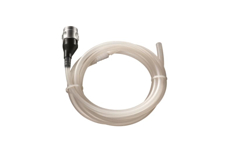
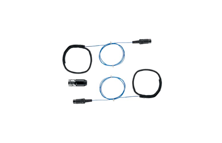
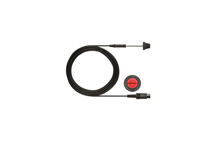
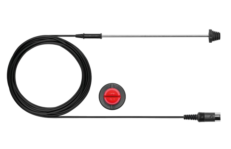
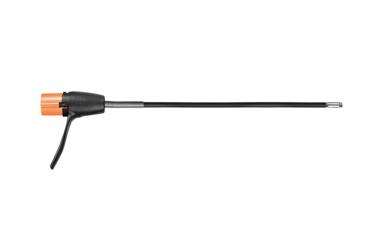
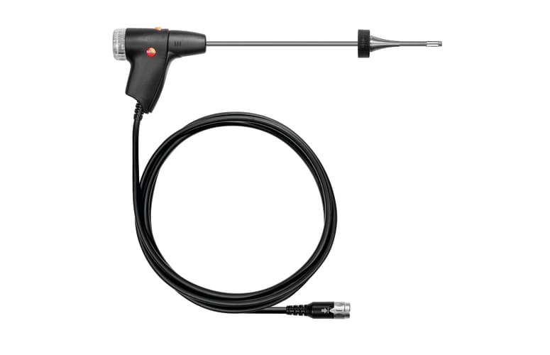
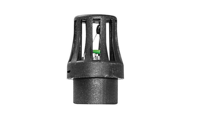
    The testo 320 flue analyzer comes with one sensor for O2 and additionally you can order a CO sensor (separate product). The flue gas analyzer then calculates the relevant flue gas values, i.e. CO2 value, efficiency and flue gas loss.
    There is also wide range of optional sensors for you to choose from. These include multiple-hole, edge crack and flexible flue gas sensors as well as an ultra-fine flue gas pressure sensor which allows you to perform draft and gas pressure measurements parallel to the other measurements.


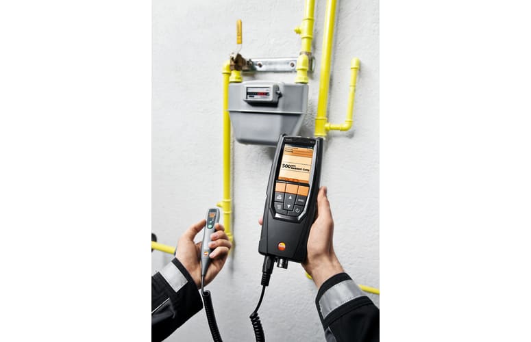
    Areas of application for the testo 320 flue gas analyzer

    Six applications. One device:
    • flue gas measurements
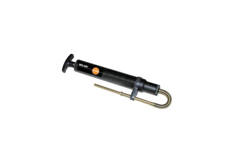
    • flue draft measurements
    • gas flow and static gas pressure
    • gas leak detection
    • CO ambient air measurements
    • temperature difference measurements
    Allows you to monitor and check heating environments, radiators and burners easily and reliably.

    testo 320 flue gas analyzer, O2 sensor.

    General technical data

    Weight
    573 g
    Dimensions
    240 x 85 x 65 mm
    Operating temperature
    -5 to +45 °C
    Display size
    240 x 320 pixels
    Display function
    Colour graphic display
    Power supply
    Battery: 3.7 V / 2,400 mAh; Mains unit: 6 V / 1.2 A
    Maximum memory
    500 Measurement values
    Storage temperature
    -20 to +50 °C

    Flue gas CO (with H₂-compensation)

    Measuring range
    0 to 8000 ppm
    Accuracy
    ±10 ppm or ±10 % of mv (0 to 200 ppm)
    ±10 % of mv (2001 to 8000 ppm)
    ±20 ppm or ±5 % of mv (201 to 2000 ppm)
    Resolution
    1 ppm
    Reaction time t₉₀
    < 40 s

    Flue gas COlow (with H₂-compensation)

    Measuring range
    0 to 500 ppm
    Accuracy
    ±5 % of mv (40 to 500 ppm)
    ±2 ppm (0 to 39.9 ppm)
    Resolution
    0.1 ppm
    Reaction time t₉₀
    < 40 s

    Accessories for measuring instrument

  6. Accessories for measuring instrument
    testo 320-330 case
    Instrument case (height: 130 mm) - for instrument, probes and accessories
      :
      0516 3300
    • Accessories for measuring instrument
      Spare particle filter
      Spare particle filter, compact probe; 10 off
        :
        0554 0040
      • Accessories for measuring instrument
        Smoke tester with oil, soot sheet, for measuring soot in flu...
        Smoke tester with oil and soot sheet, for measuring soot in flue gas
          :
          0554 0307
        • Ambient CO measurement in the heated environment

          Carbon monoxide (CO) is a colourless, odourless and taste-free gas, but also poisonous. It is produced during the incomplete combustion of substances containing carbon (oil, gas, and solid fuels, etc.). If CO manages to get into the bloodstream through the lungs, it combines with haemoglobin thus preventing oxygen from being transported in the blood; this in turn will result in death through suffocation. This is why it is necessary to regularly check CO emissions at the combustion points of heating systems and the surroundings.

          Measuring the flue gas parameters of the burner (CO, O2, and temperature, etc.)

          The flue gas measurement for a heating system helps to establish the pollutants released with the flue gas (e.g. carbon monoxide CO or carbon dioxide CO2) and the heating energy lost with the warm flue gas. In some countries, flue gas measurement is a legal requirement. It primarily has two objectives:


          • Ensuring the atmosphere is contaminated as little as possible by pollutants; and
          • energy is used as efficiently as possible.


          Stipulated pollutant quantities per flue gas volume and energy losses must never be exceeded. Measurement in terms of results required by law takes place during standard operation (every performance primarily using the appliance). Using a Lambda probe (single hole or multi-hole probe), the measurement is taken at the centre of flow in the connecting pipe (in the centre of the pipe cross-section, not at the edge) between the boiler and chimney/flue. The measured values are recorded by the flue gas analyzer and can be logged either for print out or transfer to a PC at a later stage.

          Measurement is taken by the installer at commissioning, and if necessary four weeks later by the flue gas inspector/chimney sweep, and then at regular intervals by the authorised service engineer.

          Measuring pressure on burners (nozzle pressure, gas flow pressure, etc.)

          Standard readings taken during services of domestic heating systems include checking the gas pressure on the burners. This involves measuring the gas flow pressure and gas resting pressure. The flow pressure, also called supplied pressure, refers to the gas pressure of the flowing gas and resting pressure of the static gas. If the flow pressure for gas boilers is slightly outside the 18 to 25 mbar range, adjustments must not be made and the boiler must not be put into operation. If put into operation nonetheless, the burner will not be able to function properly, and explosions will occur when setting the flame and ultimately malfunctions; the burner will therefore fail and the heating system will shut down.

          Measuring temperatures on radiators

          When measuring the temperature on radiators, the flow and return temperatures are recorded in particular and assessed by the tradesman. The flow temperature is defined as the temperature of a thermal transfer medium (e.g. water) that the system is supplied with. The temperature of the medium flowing out of the system is accordingly called the return temperature. To prevent losses within the heat distribution system and achieve a better level of efficiency in modern, heating technology, spot recording of flow and return temperatures is necessary at certain radiator pipes or screw fittings. Implementation of relevant measures ultimately leads to hydraulic adjustment on the basis of knowledge about the flow and return temperatures. This defines a procedure with which every radiator or heating circuit of a flat radiator within a heating system is supplied at a set flow temperature with the precise amount of heat needed to achieve the ambient temperature required for the individual rooms. Flawed operating conditions will result in considerable excess consumption of electricity and heating energy.

          • If the firmware update does not start under Windows 8.1 or Windows 10, a new bootloader must be installed on the measuring device once.
            A description and all necessary files can be found under the search term: Update-Kit / Bootloader
          • Testo ZIV driver in the 2000 version. The Testo ZIV driver is used to connect the testo 320 and testo 330 measuring instruments to an application program (sweeping district administration program) according to the interface Version 2.0 defined by the Zentralverband des Schornsteinfegerhandwerks (Central Association of Chimney Sweeps, ZIV). Please check with the manufacturer of your application program as to whether this interface is supported. If Microsoft .NET Framework 4.0 has not been installed on the computer, it must be downloaded from the Microsoft website and installed on the system.
          • The Testo ZIV driver is used to connect the testo 300, testo 320 and testo 330 measuring instruments to an application program (sweeping district administration program) according to the interface defined by the Zentralverband des Schornsteinfegerhandwerks (ZIV, Central Association of Chimney Sweeps) in version 1.0 of 01. August 2012, in version 2.0 of 13. February 2017 as well as version 3.0 from 02. July 2021. Please check with the manufacturer of your application program as to whether this interface is supported.
          • testo 320 Bootloader(v1.18, 384.0 kB)
          • Manual for firmware-update(v1.06, pdf, 348.21 kB)
          • Update-Kit / Bootloader(V1.22, 1.24 MB)
            (testo 330 LL | testo 330i | testo 350 Control Unit + Analysis Box | testo 320)
            If the firmware update does not start under Windows 8.1 or Windows 10, a new bootloader must be installed on the measuring device once.